The thermal shock test chamber is a cornerstone of environmental-reliability testing. Within tens of seconds it transfers specimens between extreme high- and low-temperature zones, revealing mechanical stress, electrical degradation, and chemical instability induced by rapid thermal expansion and contraction. This paper systematically summarizes the working principle, typical application fields, key technical indices, structural features, safety strategies, and energy-saving technologies of modern chambers, and uses mainstream commercial designs as examples to provide guidance for equipment selection and process optimization in research institutes, calibration laboratories, and industrial enterprises.

Test Principle and Standards
1.1 Purpose
By repeatedly subjecting specimens to “sudden cold–sudden heat” transitions, a steep transient temperature gradient is generated inside the material, accelerating the exposure of latent defects such as solder fatigue, package cracking, seal failure, and coating flaking. The failure-excitation efficiency is 3–5 times higher than that of conventional constant-temperature ageing, so the method is extensively used in product development, quality screening, and reliability qualification.
1.2 Test Modes
The two prevailing constructions are the two-zone (basket-transfer) and three-zone (static-air) types. In the two-zone version a pneumatic mechanism moves the specimen between hot and cold compartments within ≤10 s. The three-zone version adds an ambient compartment; hot and cold air streams are alternately blown over the stationary specimen, reducing the transition interval to ≤5 s, which is preferred for temperature-sensitive semiconductor devices.
1.3 Reference Standards
IEC 60068-2-14, IEC 60749, MIL-STD-202, MIL-STD-883, AEC-Q100/Q200, GB/T 2423.22, and GJB 150.5A all prescribe test conditions, transfer times, dwell periods, and recovery requirements. Depending on the service environment, temperature spans range from ?65 °C to +200 °C, and cycle numbers vary from a few dozen to over one thousand.
Application Fields
2.1 Defence, Aerospace, and Military
Satellite power modules, inertial navigation devices, and missile-borne circuits must operate reliably between ?55 °C and +125 °C under vacuum radiation. Thermal-shock screening can reduce field-failure probability by an order of magnitude by detecting gold–aluminium bond fatigue and ceramic-package micro-cracks.
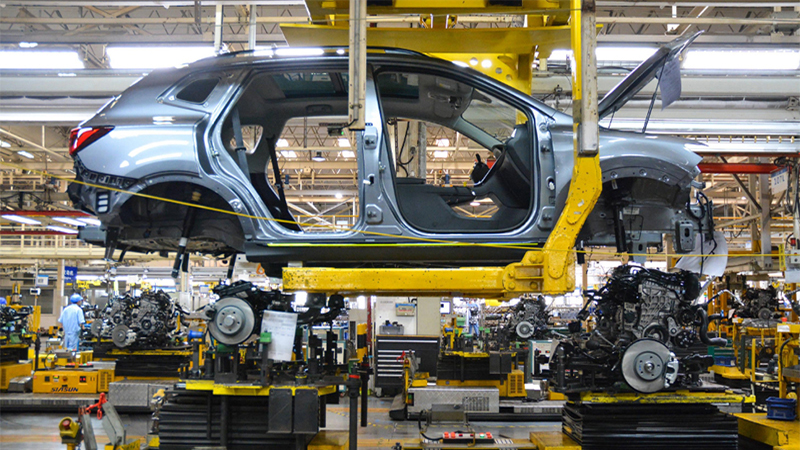
2.2 Automotive and Rail Transport
Power semiconductors, battery-management systems, sensors, and plastic lighting components on new-energy vehicles are required to withstand ?40 °C to +150 °C. After 100 cycles insulation resistance must fall by ≤10 % and sealing must remain at IP67, forming a de-facto entry barrier for Tier-1 suppliers.
2.3 Information and Telecommunications
5G RF front-ends, optical transceivers, and fibre connectors exposed to high RF power and outdoor day–night temperature swings may suffer channel-insertion-loss drift. Thermal-shock testing can simulate ten years of temperature cycling and guarantee signal integrity over the product lifetime.
2.4 Chemical Industry and Advanced Materials
Fluoro-silicone rubbers, epoxy resins, and carbon-fibre composites may exhibit glass-transition-temperature (Tg) shifts and interface debonding. Comparing DMA and SEM micrographs before and after testing optimises formulations and curing processes.
2.5 Consumer Electronics and Home Appliances
Multi-layer PCBs, camera modules, and Li-ion packs in smart phones must pass a “quality gate” of 200 cycles between ?30 °C and +85 °C. Typical failure modes—solder-ball micro-cracking, FPC rupture, and battery swelling—are fed back to the DFX platform for closed-loop improvement.
Key Technical Specifications
3.1 Temperature Range & Stability
Premium models cover ?75 °C to +220 °C with fluctuations ≤±0.3 °C and uniformity ≤±2 °C, meeting AEC-Q100 Grade 0.
3.2 Transfer Time
Basket-transfer ≤10 s; three-zone air-switching ≤5 s. Liquid-nitrogen assist can shorten transfer to 3 s, but operating cost must be weighed.
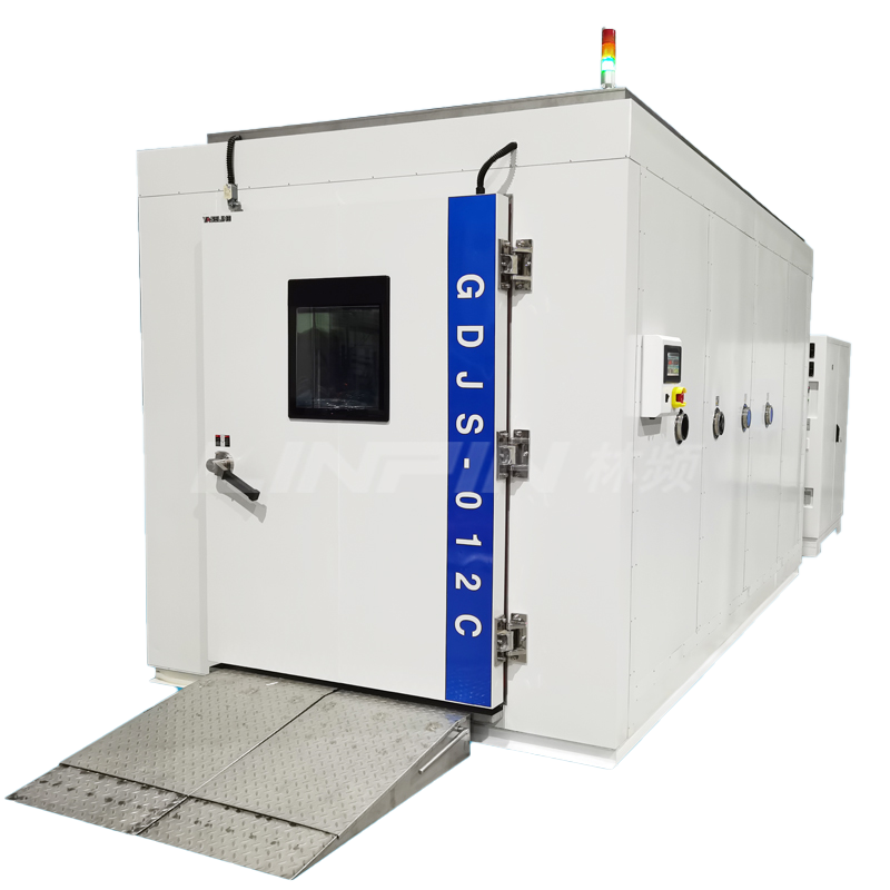
3.3 Load Capacity
A standard 50 L chamber can hold a 10 kg aluminium heat sink; a 1 000 L walk-in cabin can accept a 200 kg battery pack and is provided with an explosion-relief port.
3.4 Data Logging & Traceability
FDA 21 CFR Part 11-compliant audit trails, ≤1 s temperature sampling, USB/Ethernet/MQTT upload to MES/ERP, enabling one-item-one-code life-cycle management.
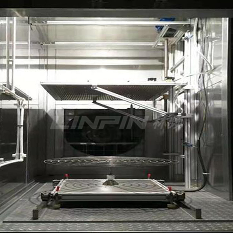
Typical Structural Design
4.1 Insulation Envelope
Inner tank: 1.2 mm 316 L stainless steel; outer shell: cold-rolled steel with twin-layer electrostatic powder coating; 150 mm high-density polyurethane + VIP vacuum panels keep surface temperature rise ≤10 °C and reduce heat leakage.
4.2 Refrigeration System
Cascade dual-loop: high-stage R-404A, low-stage R-23 or R-508B, electronic expansion valve and inverter compressor pull the cold zone to ?65 °C within 5 min; ODP = 0, GWP 50 % lower than legacy schemes.
4.3 Heating System
Ni-Cr finned heaters with ≥1.3× power redundancy, SSR zero-cross triggering, suppress surge current, life ≥20 000 h.
4.4 Control System
ARM Cortex-M7 dual-core PLC, 7″/12″ colour touchscreen, PID auto-tune & fuzzy adaptive algorithm completes thermal-mass compensation within 30 s; 32 G eMMC stores 10 years of data.
4.5 Safety Protection
Independent hardware over-temperature protector (IEC 60730), compressor high/low pressure, oil differential, phase-loss/reversal, 30 mA earth-leakage breaker, specimen-zone thermal fuse, emergency stop, tower light and SMS alarm provide multiple redundancy, ensuring zero fire, zero explosion, zero frost-bite.
Energy-Saving & Eco-Technologies
5.1 Inverter Energy Regulation
DC inverter compressor + electronic expansion valve dynamically match cooling capacity to heat load, saving 25 %–35 % compared with fixed-frequency units.
5.2 Heat-Recovery Defrost
The low-zone evaporator is switched to condenser during heat-up, transferring waste heat to the hot zone and saving 1.5 kW·h per cycle.
5.3 Smart Sleep
If idle >30 min, compressor and fans shut down automatically, holding standby power ≤0.3 kW and cutting annual CO? emission by ~3.2 t (0.718 t CO?/MW·h).
5.4 Green Refrigerants
EU F-Gas rules will phase out refrigerants with GWP>2 500 by 2025. New-generation R-469B and R-455A (GWP<150) are ASHRAE-certified and drop-in compatible with existing POE oils.
Comparison of Mainstream Commercial Designs
Taking a domestic brand (LINPIN TS series) as an example: modular construction allows 100 L–1 000 L on one platform; 4G/5G dual-SIM cloud gateway; MTBF≥8 000 h. Compared with international brands, acquisition cost is 30 % lower, maintenance response is shortened from 72 h to 24 h, and spare-part lead time is halved. The units are in service in several national calibration centres and OEM plants.
Selection, Installation, and Maintenance
7.1 Selection Strategy
Choose volume and temperature range based on specimen size, thermal mass, test standard, and takt time; for high-power devices add 20 % cooling margin after dynamic-heat-load calculation.
7.2 Installation Requirements
Ambient 5 °C–30 °C, RH≤85 %, well ventilated, ≥80 cm service clearance; air- or water-cooled, the latter needing softened water to prevent plate heat-exchanger fouling.
7.3 Routine Maintenance
Monthly: check compressor pressures, oil level, refrigerant leak; quarterly: calibrate sensors to ±0.1 °C; yearly: replace dryer filter and compressor oil, clean condenser fins to keep COP from degrading.
7.4 Fault Diagnosis
“Low temperature not reached” or “transfer time extended” usually points to electronic expansion-valve stepper, solenoid coil, or moisture excess. Built-in self-diagnosis database can locate the faulty component within 10 min, MTTR≤2 h.
Conclusion
With the rapid iteration of new-energy vehicles, 5G, and commercial aerospace, products face ever harsher environmental demands. Thermal-shock chambers—moving toward wider temperature spans, faster transfer, tighter control, and lower energy consumption—are becoming indispensable reliability tools. Users should fully understand applicable standards and failure mechanisms, select rationally, operate strictly, and maintain meticulously to maximise equipment value, shorten R&D cycles, and reduce life-cycle costs, thereby gaining a dual advantage in quality and brand in today’s fierce market competition.


Copyright ? 2025 Shanghai Linpin Instrument Co., Ltd Copyright
| ICP Number:Shanghai ICP Record No. 12029585-7
| Sitemap

<strike id="00ggy"></strike>


 EN
EN
 中文
中文 Pусский
 Ti?ng Vi?t
 ???????
 ???????? ????